Controlling a 3D Printer's Power Supply with OctoPrint
🗓️ • ⏱️ 5 min read
🗓️ • ⏱️ 5 min read
This will probably be the first in a series of posts about my journeys tinkering with my stock Creality Ender 3 printer. One of the first things I wanted to do after buying the Ender 3 back in August 2020 was the ability to power on/off the printer via the OctoPrint interface. Luckily there is a robust PSU Control plugin that already exists. I just needed to figure out the hardware. I was also able to find this Raspberry Pi enclosure for the Ender 3 on Thingiverse which I’ve remixed to add a hole for a female barrel connector.
There are various other tutorials about similar setups but none that match exactly what I was looking to do. Hopefully this can help others looking to do the same. Having said that this is by no means the right or best way to do this. It is just the way that worked best for me after a few iterations.
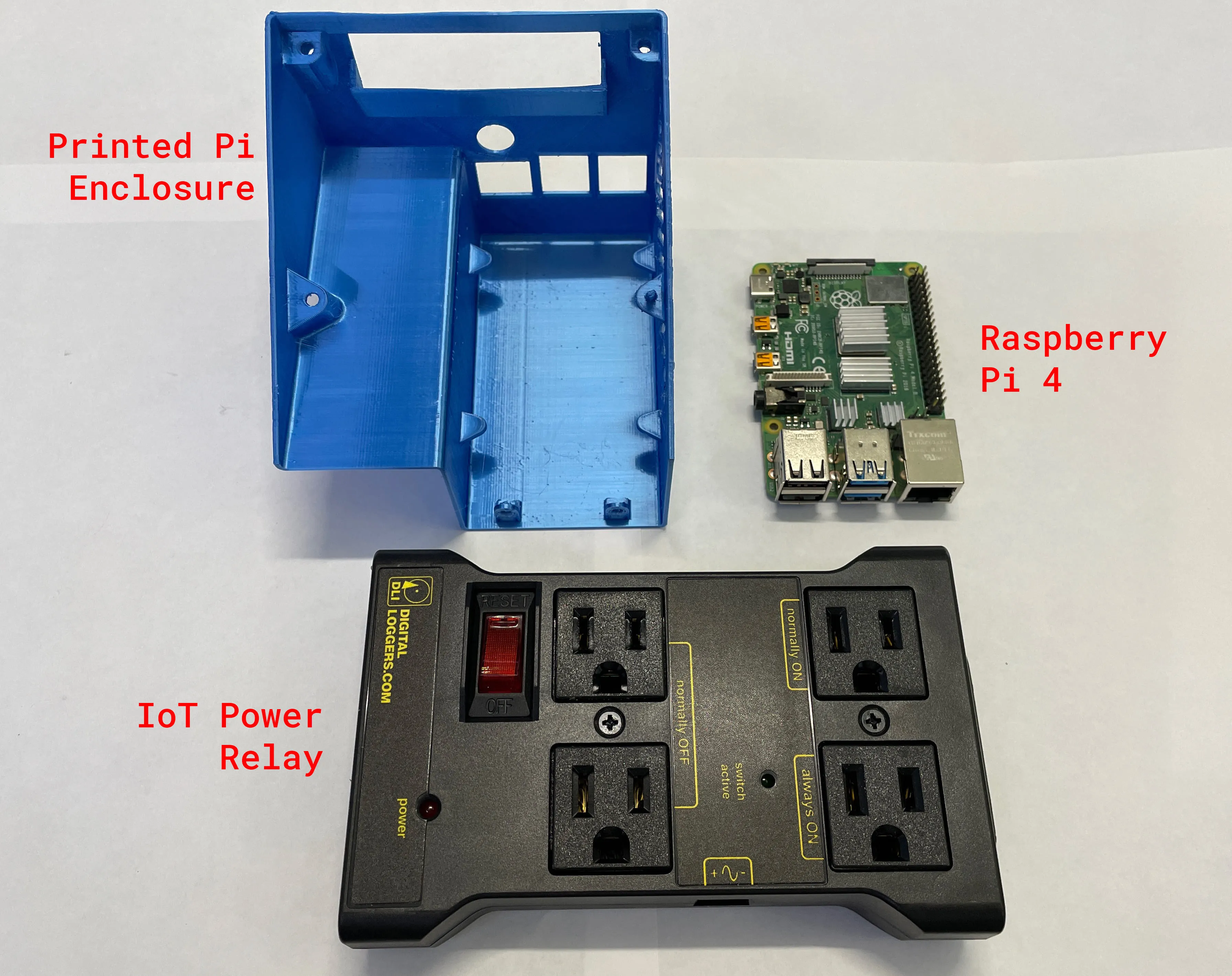
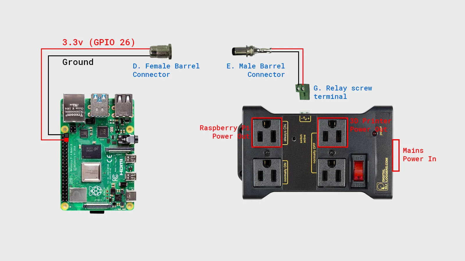
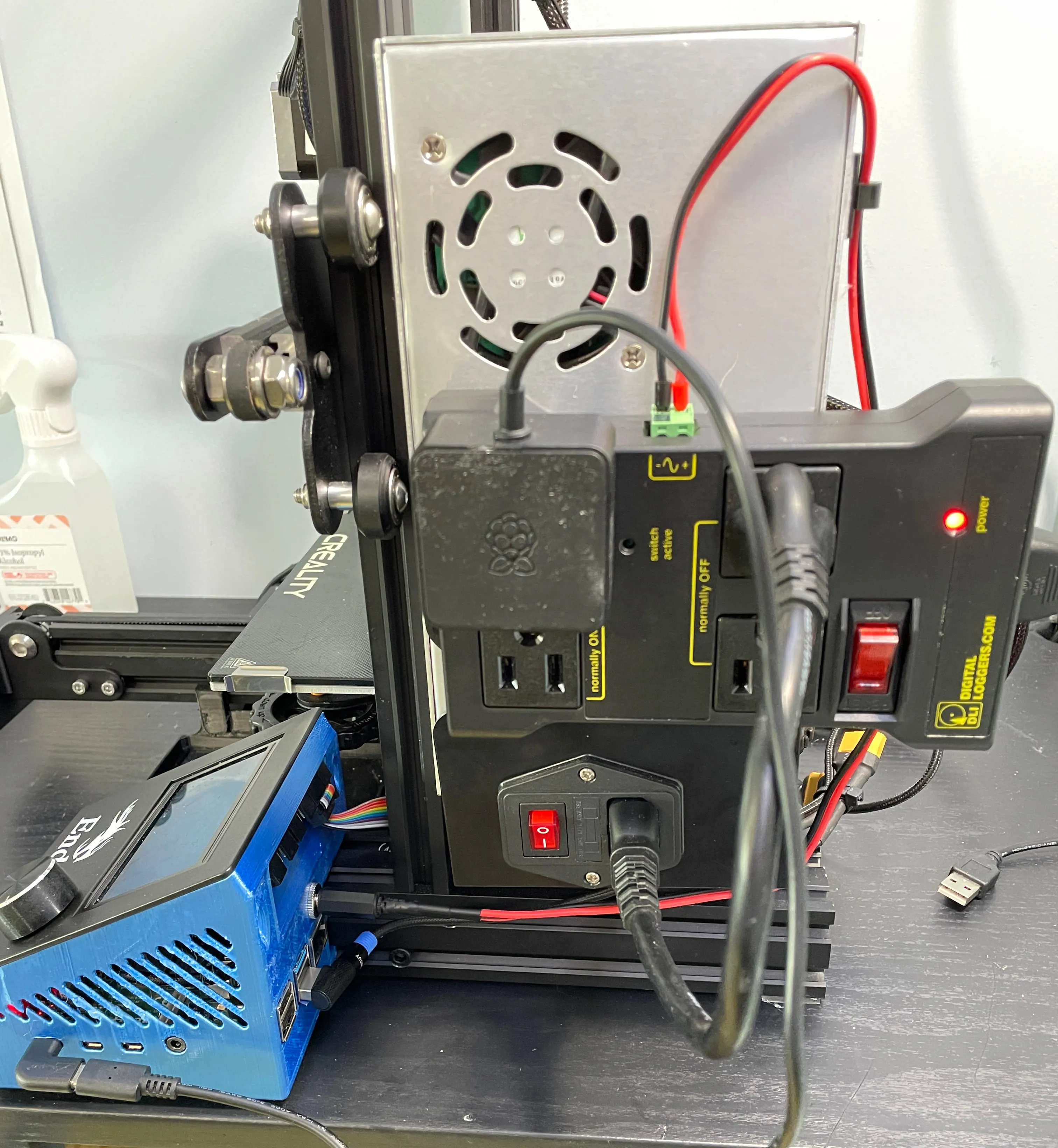
Mains power is provided to the IoT Power Relay. The “Always On” outlet provides constant power to the Raspberry Pi. By plugging the power cord from the printer’s power supply into the “Normally Off” outlet power will not be provided until the Raspberry Pi sends a 3.3v signal to the IoT Power Relay via the wiring we set up.
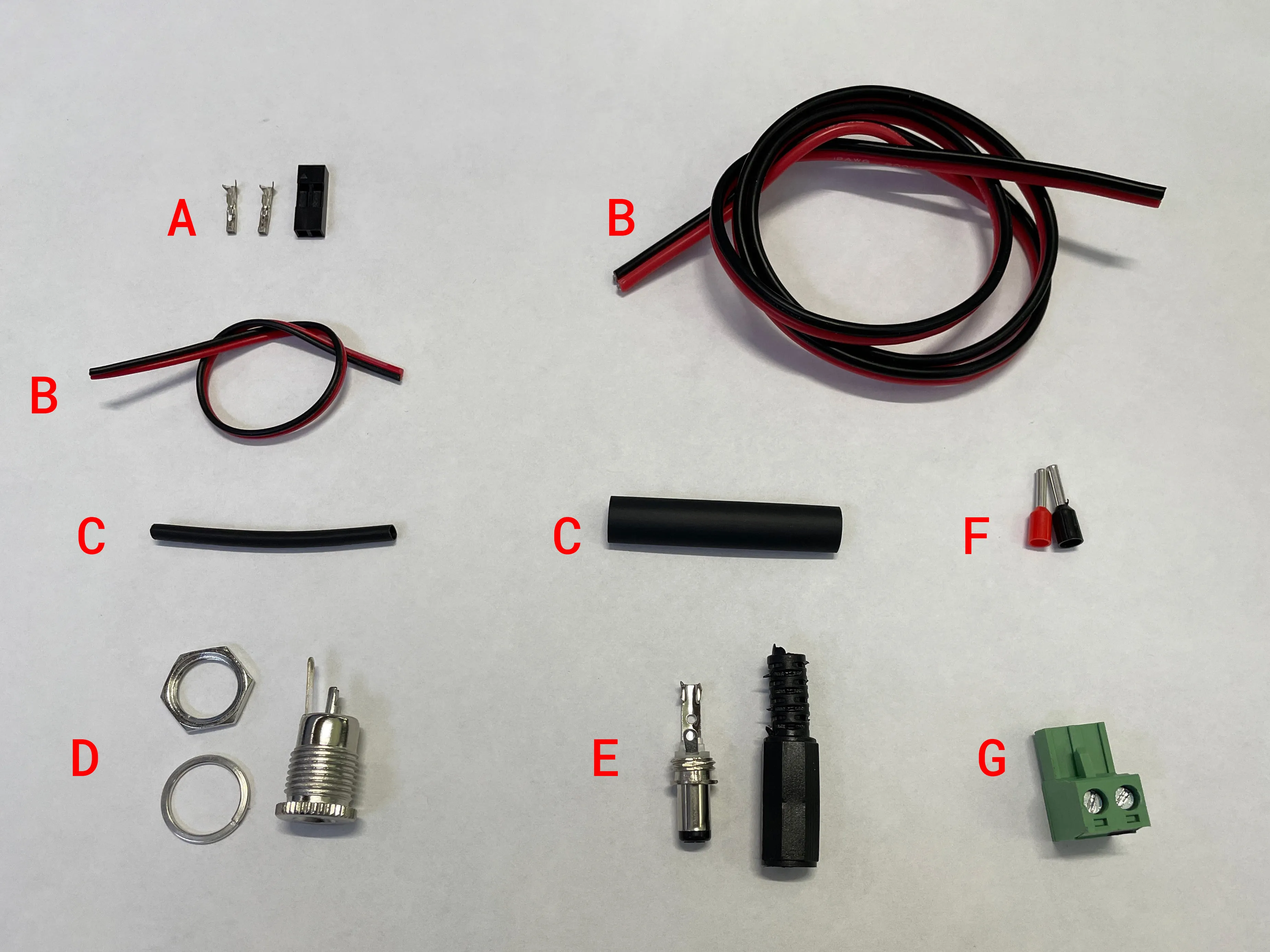
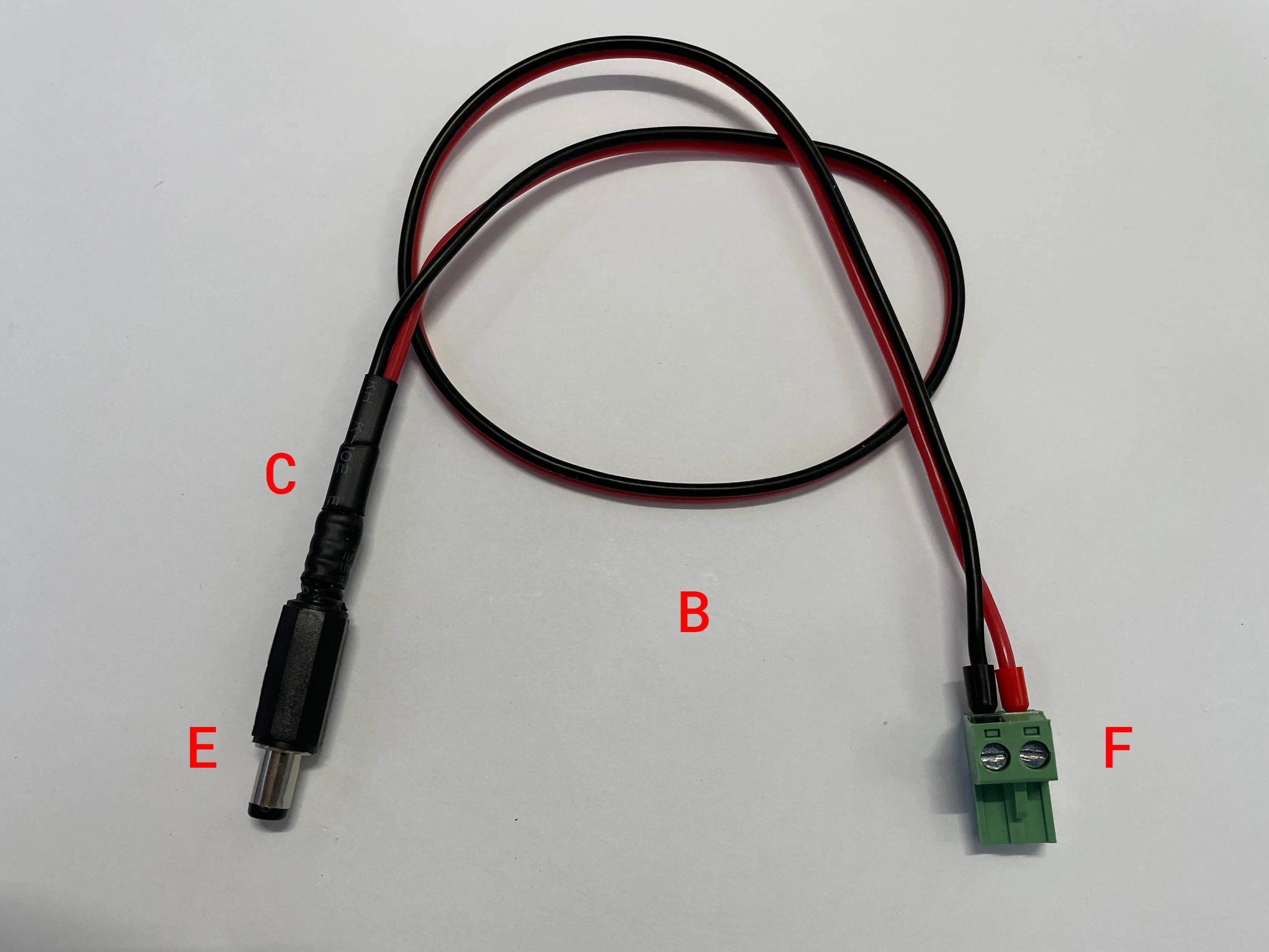
For the connection between the RPi and the printed enclosure we need a short length of relatively short wire (about 50cm) B. Ground should be soldered to the larger terminal on the female barrel connector D and power to the smaller terminal. Wrap them in heat shrink C. On the other end of the wire crimp and connect the 2-pin Dupont connector A.
For the connection between the printed enclosure and the PSU controller we again need to solder the ground wire to the larger terminal and power to the smaller terminal of the male barrel connector E. Again covering both in heat shrink C. The other end can be either crimped with ferrules F or plugged right into the PSU connector G.
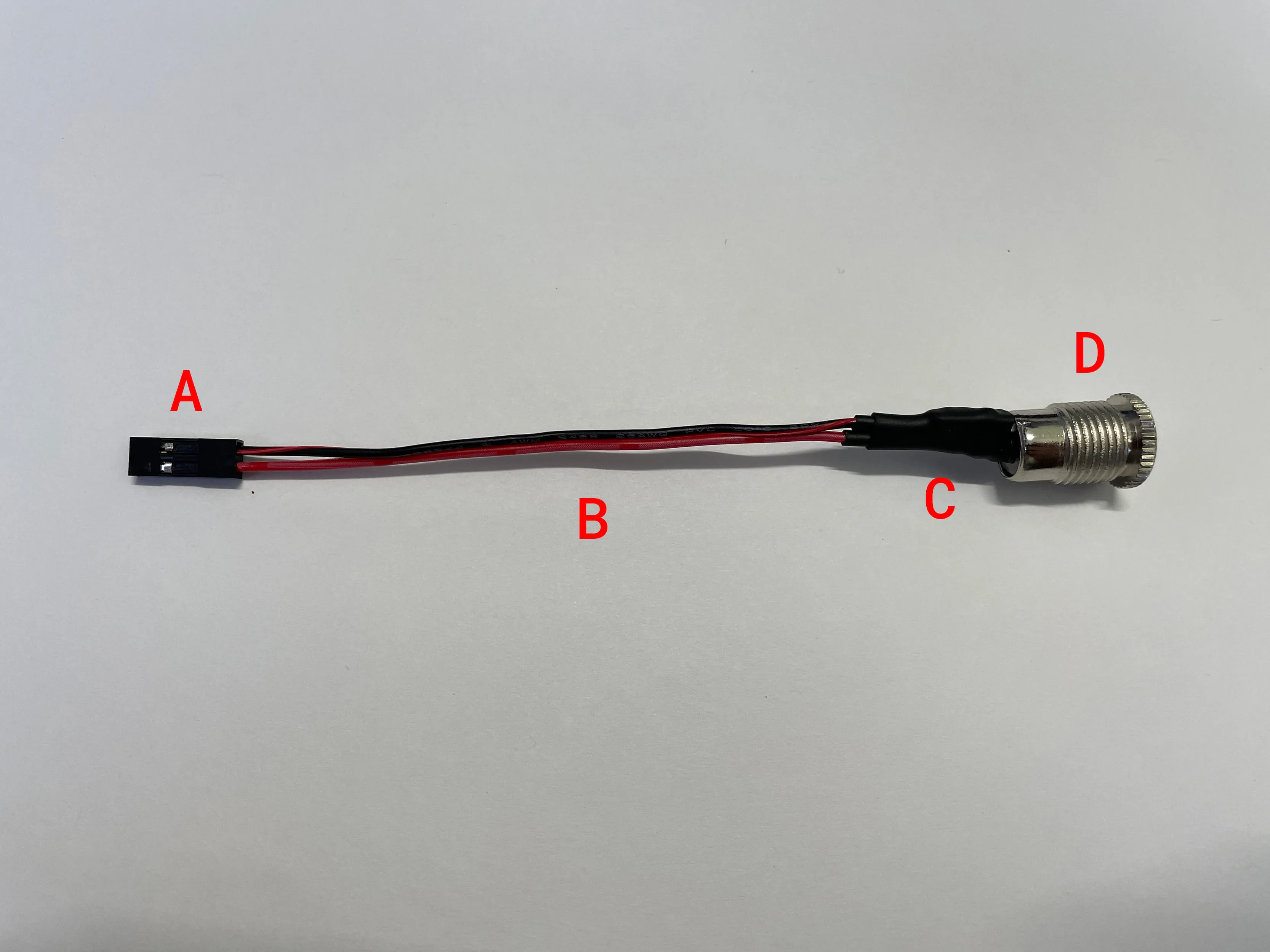
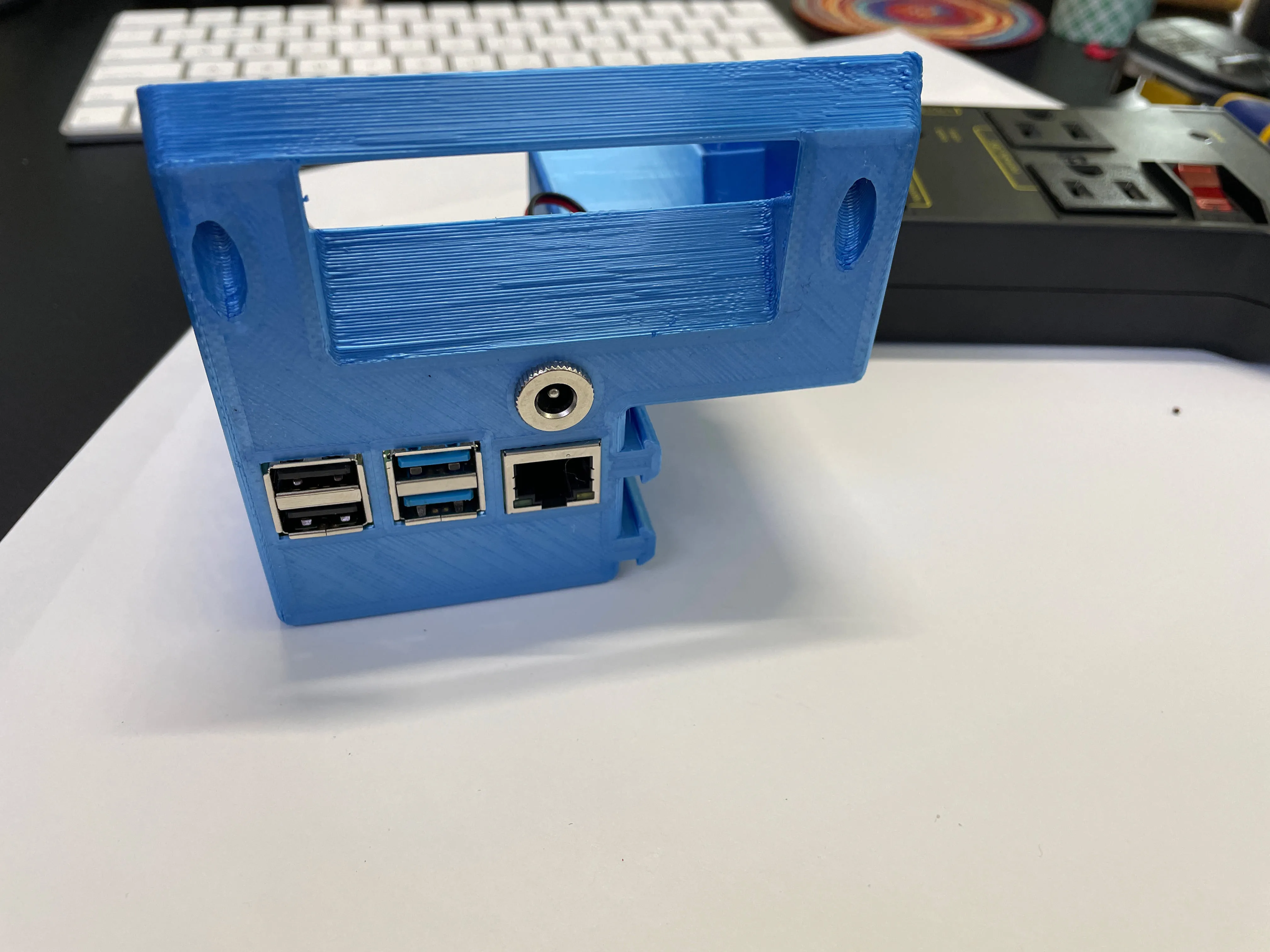
Feed the dupont end of the wire through the hole in the print enclosure until the ring of the female barrel connector sits flush with the printed enclosure. Slide the washer and locking nut over the wire and hand tighten until the barrel connector feels snug.
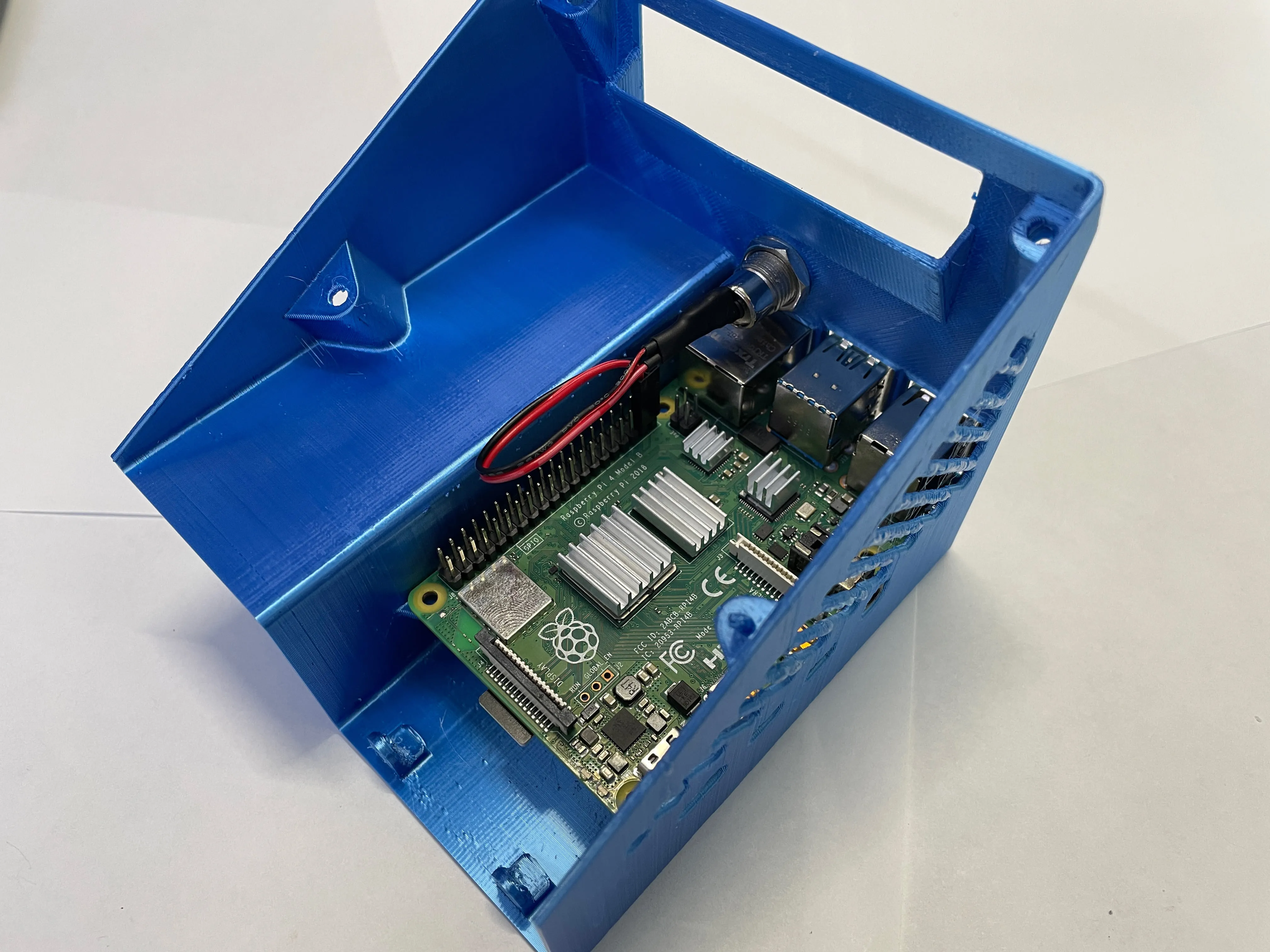
Fit the Pi into the case and plug the dupont connector into the GPIO header. Physical pin 37 for red and physical pin 39 for black.
I just used some double stick tape to adhere the Power Relay to my Ender 3’s power supply. This allowed me to have the shortest possible lengths for both the wire from the Raspberry Pi to the power relay and the cord from the power relay to the power supply.
The Pi enclosure slides into the aluminum extrusion of the Ender 3 and then wire connections can be made.
Install the following two plugins to your OctoPrint instance.
GPIO26Enable switching with G-Code commands.M80M81PluginPSU Control - RPI.GPIO1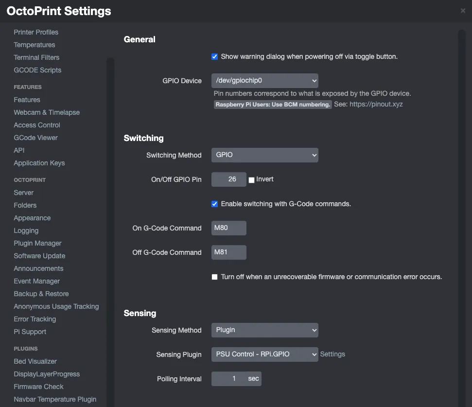
BCM2626 Float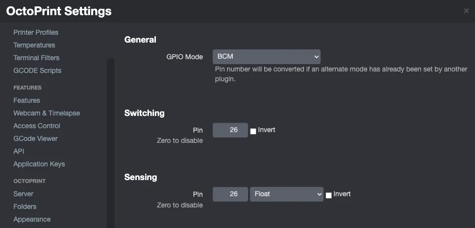
Save your settings and refresh OctoPrint. You should now have a lightning bolt icon in the top nav bar that you can use to turn on and off your printer.

You should be all set now. Again, this might not be the right or best way to do it. However it is what works for me. If you have any comments or questions feel free to reach out to me via email johnzanussi [at] gmail.com.
Found the above useful? Have a question? Thought of something I didn't?
Consider leaving a comment below or send me an email at johnzanussi@gmail.com.
You can also buy me a coffee. Cheers!

Comments